Keyestudio Robotale Scratch
Contents (Hızlı Menü)
Keyestudio Robotale Scratch
Tanıtım
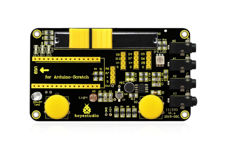
keyestudio Robotale Scratch, Arduino Nano ile birlikte kullanılır. Scratch programlama dilini kullanarak, Arduino ile kolayca basit etkileşimli programlar oluşturabilir veya Arduino'nun sensörlerden verilerini temel alan programlar oluşturabilirsiniz. keyestudio Robotale Scratch, bir ışık sensörü, ses sensörü, bir düğme ve bir sürgü potun yanı sıra kablolarla elektriksel direnci algılamak üzere 4 ek giriş içerir. Eğitimciler ve yeni başlayanlar için tasarlandı. Keyestudio Robotale Scratch, programlama ve okuma sensörleri için en temel temel öğrenme yoludur.
Özellikler
- Nano geliştirme kartıyla kullanım
- Bir ışık sensörü, ses sensörü, bir düğme ve bir sürgü potu yerleşiktir
- S4A basit programlama
Kullanma Talimatı
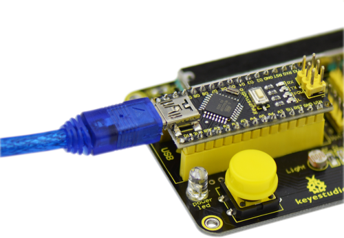
1. Nano geliştirme kartını bilgisayara bağlayın, ürün yazılımını yüklemek için Arduino IDE kullanın.
2. S4A'yı açın, yeni kostümler edinmek için "Kostümler" e tıklayın.
3. "Script" e tıklayın, kontrol grubu bloklarını kullanarak kontrol komut dosyasını yazın.
4. Kontrol komut dosyasını tamamladıktan sonra, komut dosyasını çalıştırmak için  sembolüne tıklayın.
Circuit Connection / Devre Bağlantısı
Sample Code / Örnek Kod
You can directly copy the below code.
Aşağıdaki kodu doğrudan kopyalayabilirsiniz.
// NEW IN VERSION 1.5:
// Changed pin 8 from standard servo to normal digital output

// NEW IN VERSION 1.4:
// Changed Serial.print() for Serial.write() in ScratchBoardSensorReport function to make it compatible with latest Arduino IDE (1.0)

// NEW IN VERSION 1.3:
// Now it works on GNU/Linux. Also tested with MacOS and Windows 7.
// timer2 set to 20ms, fixing a glitch that made this period unstable in previous versions.
// readSerialport() function optimized.
// pulse() modified so that it receives pulse width as a parameter instead using a global variable.
// updateServoMotors changes its name as a global variable had the same name.
// Some minor fixes.

// Thanks to Jorge Gomez for all these new fixes!

#define TIMER2_PRELOAD 100

char outputs[10];
int states[10];

unsigned long initialPulseTime;
unsigned long lastDataReceivedTime;

volatile boolean updateServoMotors;
volatile boolean newInterruption;

void setup()
{
 Serial.begin(38400);
 Serial.flush();
 configurePins();
 configureServomotors();
 lastDataReceivedTime = millis();
}

void loop()
{
 if (updateServoMotors)
 {
   sendUpdateServomotors();
   sendSensorValues();
   updateServoMotors = false;
 }
 else
 {
   readSerialPort();
 }
}

void configurePins()
{
 for (int index = 0; index < 10; index++)
 {
    states[index] = 0;
    pinMode(index+4, OUTPUT);
    digitalWrite(index+4, LOW); //reset pins
 }

 pinMode(2,INPUT);
 pinMode(3,INPUT);

 outputs[0] = 'c'; //pin 4
 outputs[1] = 'a'; //pin 5
 outputs[2] = 'a'; //pin 6
 outputs[3] = 'c'; //pin 7
 outputs[4] = 's'; //pin 8
 outputs[5] = 'a'; //pin 9
 outputs[6] = 'd'; //pin 10
 outputs[7] = 'd'; //pin 11
 outputs[8] = 'd'; //pin 12
 outputs[9] = 'd'; //pin 13
}

void configureServomotors() //servomotors interruption configuration (interruption each 10 ms on timer2)
{
 newInterruption = false;
 updateServoMotors = false;

 TCCR2A = 0;
 TCCR2B = 1< 0) && ( array[j] < array[j-1] ); j--)
      swap( array, j, j-1 );
}

void swap (int* array, int a, int b)
{
  int temp = array[a];
  array[a] = array[b];
  array[b] = temp;
}

void ScratchBoardSensorReport(int sensor, int value) //PicoBoard protocol, 2 bytes per sensor
{
  Serial.write( B10000000
                | ((sensor & B1111)<<3)
                | ((value>>7) & B111));
  Serial.write( value & B1111111);
}

void readSerialPort()
{
  int pin, inByte, sensorHighByte;

  if (Serial.available() > 1)
  {
    lastDataReceivedTime = millis();
    inByte = Serial.read();

    if (inByte >= 128) // Are we receiving the word's header?
    {
      sensorHighByte = inByte;
      pin = ((inByte >> 3) & 0x0F);
      while (!Serial.available()); // Wait for the end of the word with data
      inByte = Serial.read();
      if (inByte <= 127) // This prevents Linux ttyACM driver to fail
      {
        states[pin - 4] = ((sensorHighByte & 0x07) << 7) | (inByte & 0x7F);
          updateActuator(pin - 4);
      }
    }
  }
  else checkScratchDisconnection();
}

void reset() //with xbee module, we need to simulate the setup execution that occurs when a usb connection is opened or closed without this module
{
  for (int pos = 0; pos < 10; pos++)  //stop all actuators
  {
    states[pos] = 0;
    digitalWrite(pos + 2, LOW);
  }

  //reset servomotors
  newInterruption = false;
  updateServoMotors = false;
  TCNT2 = TIMER2_PRELOAD;

  //protocol handshaking
  sendSensorValues();
  lastDataReceivedTime = millis();
}

void updateActuator(int pinNumber)
{
  if (outputs[pinNumber] == 'd')  digitalWrite(pinNumber + 4, states[pinNumber]);
  else if (outputs[pinNumber] == 'a')  analogWrite(pinNumber + 4, states[pinNumber]);
}

void sendUpdateServomotors()
{
  for (int p = 0; p < 10; p++)
  {
    if (outputs[p] == 'c') servomotorC(p + 4, states[p]);
    if (outputs[p] == 's') servomotorS(p + 4, states[p]);
  }
}

void servomotorC (int pinNumber, int dir)
{
  if (dir == 1) pulse(pinNumber, 1300); //clockwise rotation
  else if (dir == 2) pulse(pinNumber, 1700); //anticlockwise rotation
}

void servomotorS (int pinNumber, int angle)
{
  if (angle < 0) pulse(pinNumber, 600);
  else if (angle > 180) pulse(pinNumber, 2400);
  else pulse(pinNumber, (angle * 10) + 600);
}

void pulse (int pinNumber, int pulseWidth)
{
  initialPulseTime = micros();
  digitalWrite(pinNumber, HIGH);

  while (micros() < pulseWidth + initialPulseTime){}
  digitalWrite(pinNumber, LOW);
}

void checkScratchDisconnection() //the reset is necessary when using an wireless arduino board (because we need to ensure that arduino isn't waiting the actuators state from Scratch) or when scratch isn't sending information (because is how serial port close is detected)
{
  if (millis() - lastDataReceivedTime > 1000) reset(); //reset state if actuators reception timeout = one second
}

ISR(TIMER2_OVF_vect) //timer1 overflow interrupt vector handler
{ //timer2 => 8 bits counter => 256 clock ticks
  //preeescaler = 1024 => this routine is called 61 (16.000.000/256/1024) times per second approximately => interruption period =  1 / 16.000.000/256/1024 = 16,384 ms
  //as we need a 20 ms interruption period but timer2 doesn't have a suitable preescaler for this, we program the timer with a 10 ms interruption period and we consider an interruption every 2 times this routine is called.
  //to have a 10 ms interruption period, timer2 counter must overflow after 156 clock ticks => interruption period = 1 / 16.000.000/156/1024 = 9,984 ms => counter initial value (TCNT) = 100
  if (newInterruption)
  {
    updateServoMotors = true;
  }
  newInterruption = !newInterruption;
  TCNT2 = TIMER2_PRELOAD;  //reset timer
}
Script Edit / Script Düzenleme
Script 1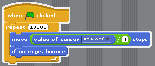
Script 2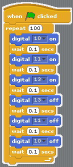
Result / Sonuç
For script 1 / Script 1 için
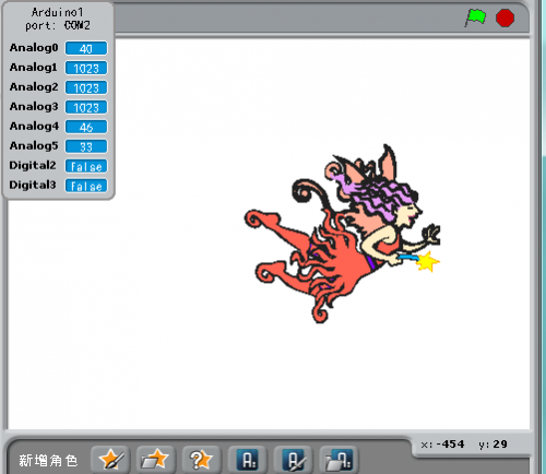
Click  , the costume moves freely; bounce back when it hits the edge. Move the slider on the shield to change the value in Analog0, the greater the value, the faster the costume moves.
 sembolüne tıklayın. Kostüm serbestçe hareket eder; kenara çarptığında geri zıplar. Analog 0'daki değeri değiştirmek için shield üzerindeki sürgüyü hareket ettirin, değer ne kadar büyük olursa, kostüm o kadar hızlı hareket eder.
For script 2 / Script 2 için
Click  , the D10, D11, D13 LEDs on the shield displays light chasing effect; stops after 100 cycles.
 sembolüne tıklayın. Shielddeki D10, D11, D13 LED'leri ışık takip efekti gösterir; 100 döngüden sonra durur.
Resources / Kaynaklar
Code Download of Robotale Scratch: / Robotale Scratch için Kod Yükleme:
https://drive.google.com/open?id=1GMZTCKu85Him4LaFBFLDHrJbIGpXVoBN
PDF:
https://drive.google.com/open?id=1CQTCCumWVlXV4kSivuVZi8ZnBgwwuVme
Video:

