Keyestudio Yeni Sensör Seti (MEGA 2560 R3 dahil)
Contents
- 1 keyestudio New sensor kit with MEGA 2560 R3 / keyestudio Yeni Sensör Kiti (MEGA 2560 R3 Dahil)
- 2 Summary / Özet
- 3 Kit list / Kit Listesi
- 4 Project details / Proje Detayları
- 4.1 Project 1: Piranha LED Module
- 4.2 Project 2: Digital white LED module
- 4.3 Project 3: Passive Buzzer module
- 4.4 Project 4: Hall Magnetic Sensor
- 4.5 Project 5: LM35 Linear Temperature Sensor
- 4.6 Project 6: 18B20 Temperature Sensor
- 4.7 Project 7: Digital Tilt Sensor
- 4.8 Project 8: Photocell sensor
- 4.9 Project 9: Digital Push Button
- 4.10 Project 10: Capacitive Touch Sensor
- 4.11 Project 11: DHT11 Temperature and Humidity Sensor
- 4.12 Project 12: Analog Sound Sensor
- 4.13 Project 13: Flame Sensor
- 4.14 Project 14: DS3231 Clock Module
- 4.15 Project 15: Analog Gas Sensor
- 4.16 Project 16: Analog Alcohol Sensor
- 4.17 Project 17: keyestudio Water Sensor
- 4.18 Project 18: Soil Humidity Sensor
- 4.19 Project 19: Infrared Obstacle Avoidance Sensor
- 4.20 Project 20: PIR Motion Sensor
- 4.21 Project 21: Joystick Module
- 4.22 Project 22: Photo interrupter module
- 4.23 Project 23: 5V Relay Module
- 4.24 Project 24: ADXL345 Three Axis Acceleration Module
- 4.25 Project 25: Rotary Encoder module
- 4.26 Project 26: Analog Rotation Sensor
- 4.27 Project 27: HC-SR04 Ultrasonic Sensor
- 4.28 Project 28: Pulse Rate Monitor
- 4.29 Project 29: Reed Switch Module
- 4.30 Project 30: TEMT6000 ambient light sensor
- 5 Resources / Kaynaklar
keyestudio New sensor kit with MEGA 2560 R3
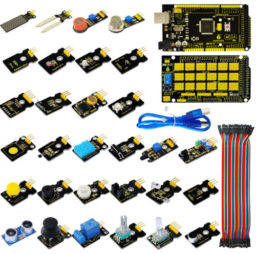
Sensor kit for Arduino
Based on open-source hardware
30 various sensors in one box
For you to make interesting projects
Summary / Özet
This is an Arduino sensor learning kit developed by Keyes. We bring together 30 basic sensors and modules, aiming for the convenience of its learning for starters. Inside this box, there are digital and analog sensors and also some special modules such as buzzer, ultrasonic, acceleration modules etc. For each module, there is clear connection diagram and sample code. So even if you are totally new at this, you can get started easily.
The sample codes for this sensor kit are based on ARDUINO because it's open source and easy. And if you are good at this, you can also apply this kit to other MCU development platform, such as 51, STM32, Raspberries Pi. The working principle is pretty much the same.
Now, let us embrace this fascinating world of ARDUINO and learn together!
Bu, Keyes tarafından geliştirilen bir Arduino sensör öğrenme kitidir. Yeni başlayanlar için öğrenmenin kolaylığını hedefleyen 30 temel sensör ve modülü bir araya getiriyoruz. Bu kutunun içinde dijital ve analog sensörler ile buzzer (sesli uyarı), ultrasonik, ivme modülü vb. bazı özel modüller bulunur. Her modül için bağlantı şeması ve örnek kod vardır. Bu konuda tamamen yeni olsanız bile kolayca başlayabilirsiniz.
Bu sensör kitinin örnek kodları ARDUINO tabanlıdır, çünkü açık kaynak kodlu ve kolaydır. Bu konuda iyiyseniz, bu kiti 51, STM32, Raspberries Pi gibi diğer MCU geliştirme platformlarına da uygulayabilirsiniz. Çalışma prensibi hemen hemen aynıdır.
Şimdi, ARDUINO'nun bu büyüleyici dünyasını kucaklayalım ve birlikte öğrenelim!
Kit list / Kit Listesi
|
1. Piranha LED Module 29. MEGA 2560 R3 Board
|
1. Piranha LED Modül 29. MEGA 2560 R3 Denetleyici
|
Project details / Proje Detayları
Project 1: Piranha LED Module
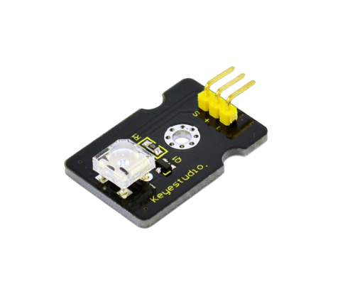
Introduction:
This is a special LED module. When you connect it to ARDUINO development board, after program, it can emit beautiful light. Of course, you can also control it using PWM. It will be like fireflies at night. Isn’t cool? We can also combine it with other sensors to do various interesting interactive experiments.
Specifications:
Module type: digital
Working voltage: 5v
Distance between pins: 2.54mm
Size: 30*20mm
Weight: 3g
Connection Diagram: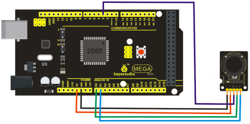
Sample Code:
int led = 3;
void setup()
{
  pinMode(led, OUTPUT);     //Set Pin3 as output
}
void loop()
{      digitalWrite(led, HIGH);   //Turn off led
          delay(2000);
          digitalWrite(led, LOW);    //Turn on led
          delay(2000);
}
Project 2: Digital white LED module
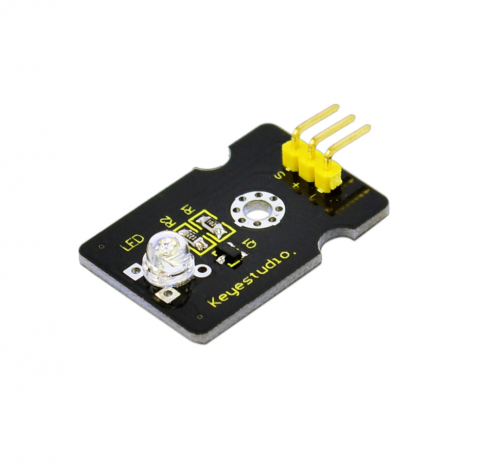
Introduction:
This LED light module has a shiny color, ideal for Arduino starters. It can be easily connected to IO/Sensor shield.
Specification:
Type: Digital
PH2.54 socket
White LED light module
Enables interaction with light-related works
Size: 30*20mm
Weight: 3g
Connection Diagram: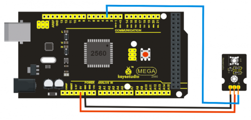
Sample Code:
int led = 3;
void setup()
{
 pinMode(led, OUTPUT);     //Set Pin3 as output
}
void loop()
{
         digitalWrite(led, HIGH);   //Turn on led
         delay(2000);
         digitalWrite(led, LOW);    //Turn off led
         delay(2000);
}
Project 3: Passive Buzzer module
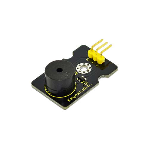
Introduction:
We can use Arduino to make many interactive works of which the most commonly seen is acoustic-optic display. All the previous experiment has something to do with LED. However, the circuit in this experiment can produce sound. Normally, the experiment is done with a buzzer or a speaker while buzzer is simpler and easier to use. The buzzer we introduced here is a passive buzzer. It cannot be actuated by itself, but by external pulse frequencies. Different frequencies produce different sounds. We can use Arduino to code the melody of a song, which is actually quite fun and simple.
Specification:
Working voltage: 3.3-5v
Interface type: digital
Size: 30*20mm
Weight: 4g
Connection Diagram: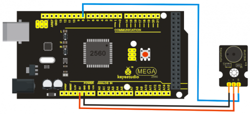
Sample Code:
int buzzer=8;//set digital IO pin of the buzzer
void setup()
{
pinMode(buzzer,OUTPUT);// set digital IO pin pattern, OUTPUT to be output
}
void loop()
{ unsigned char i,j;//define variable
while(1)
{ for(i=0;i<80;i++)// output a frequency sound
{ digitalWrite(buzzer,HIGH);// sound
delay(1);//delay1ms
digitalWrite(buzzer,LOW);//not sound
delay(1);//ms delay
}
for(i=0;i<100;i++)// output a frequency sound
{
digitalWrite(buzzer,HIGH);// sound
digitalWrite(buzzer,LOW);//not sound
delay(2);//2ms delay
} } }
After downloading the program, buzzer experiment will been finished.
Project 4: Hall Magnetic Sensor
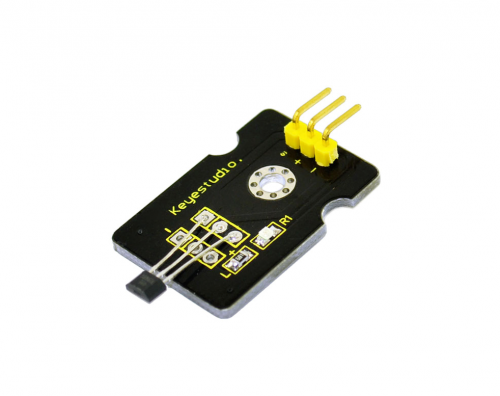
Introduction:
This is a Magnetic Induction Sensor. It senses the magnetic materials within a detection range up to 3cm. The detection range and the strength of the magnetic field are proportional. The output is digital on/off. This sensor uses the SFE Reed Switch - Magnetic Field Sensor.
Specification:
Sensing magnetic materials
Detection range: up to 3cm
Output: digital on/off
Detection range and magnetic field strength are proportional
Size: 30*20mm
Weight: 3g
Connection Diagram: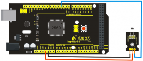
Sample Code:
int ledPin = 13;                // choose the pin for the LED
int inputPin = 3;               // Connect sensor to input pin 3
int val = 0;                    // variable for reading the pin status

void setup() {
  pinMode(ledPin, OUTPUT);      // declare LED as output
  pinMode(inputPin, INPUT);     // declare pushbutton as input
}

void loop(){
  val = digitalRead(inputPin);  // read input value
  if (val == HIGH) {            // check if the input is HIGH
    digitalWrite(ledPin, LOW);  // turn LED OFF
  } else {
    digitalWrite(ledPin, HIGH); // turn LED ON
  }
}
Project 5: LM35 Linear Temperature Sensor
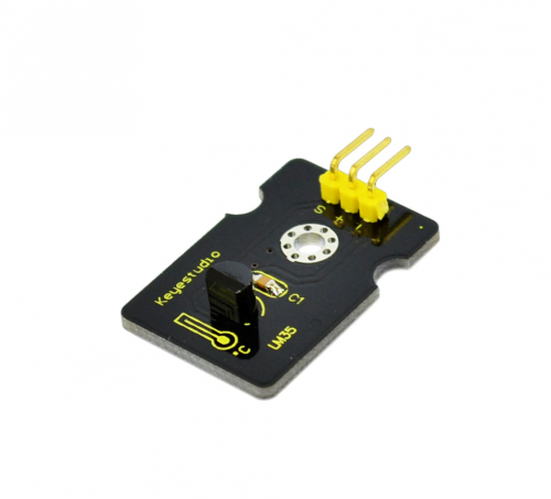
Introduction:
LM35 Linear Temperature Sensor is based on semiconductor LM35 temperature sensor. It can be used to detect ambient air temperature. This sensor offers a functional range among 0 degree Celsius to 100 degree Celsius. Sensitivity is 10mV per degree Celsius. The output voltage is proportional to the temperature.
This sensor is commonly used as a temperature measurement sensor. It includes thermocouples, platinum resistance, and thermal resistance and temperature semiconductor chips. The chip is commonly used in high temperature measurement thermocouples. Platinum resistance temperature sensor is used in the measurement of 800 degrees Celsius, while the thermal resistance and semiconductor temperature sensor is suitable for measuring the temperature of 100-200 degrees or below, in which the application of a simple semiconductor temperature sensor is good in linearity and high in sensitivity. The LM35 linear temperature sensor and sensor-specific Arduino shield can be easily combined.
Specification:
Based on the semiconductor LM35 temperature sensor
Can be used to detect ambient air temperature
Sensitivity: 10mV per degree Celcius
Functional range: 0 degree Celsius to 100 degree Celsius
Size: 30*20mm
Weight: 3g
Connection Diagram: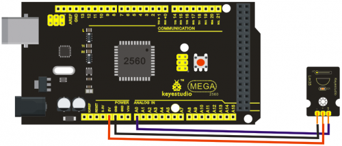
Sample Code:
void setup()
{
    Serial.begin(9600);//Set Baud Rate to 9600 bps
}
 void loop()
{
    int val;
    int dat;
    val=analogRead(0);//Connect LM35 on Analog 0
    dat=(500 * val) /1024;;
    Serial.print("Temp:"); //Display the temperature on Serial monitor
    Serial.print(dat);
    Serial.println("C");
    delay(500);
}
Project 6: 18B20 Temperature Sensor
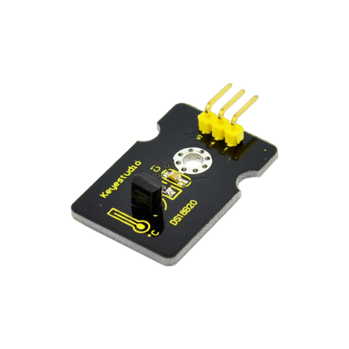
Introduction:
DS18B20 is a digital temperature sensor from DALLAS U.S. It can be used to quantify environmental temperature testing.
The temperature range is -55 ~ +125 ?, inherent temperature resolution 0.5 ?. It also support multi-point mesh networking. Three DS18B20 can be deployed on three lines to achieve multi-point temperature measurement. It has a 9-12 bit serial output.
Specification:
Supply Voltage: 3.3V to 5V
Temperature range: -55 °C ~ +125 °C
Interface: Digital
Size: 30*20mm
Weight: 3g
Connection Diagram: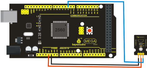
Sample Code:
http://www.pjrc.com/teensy/arduino_libraries/OneWire.zip
#includeint DS18S20_Pin = 2; //DS18S20 Signal pin on digital 2 //Temperature chip i/o OneWire ds(DS18S20_Pin); // on digital pin 2 void setup(void) { Serial.begin(9600); } void loop(void) { float temperature = getTemp(); Serial.println(temperature); delay(100); //just here to slow down the output so it is easier to read } float getTemp(){ //returns the temperature from one DS18S20 in DEG Celsius byte data[12]; byte addr[8]; if ( !ds.search(addr)) { //no more sensors on chain, reset search ds.reset_search(); return -1000; } if ( OneWire::crc8( addr, 7) != addr[7]) { Serial.println("CRC is not valid!"); return -1000; } if ( addr[0] != 0x10 && addr[0] != 0x28) { Serial.print("Device is not recognized"); return -1000; } ds.reset(); ds.select(addr); ds.write(0x44,1); // start conversion, with parasite power on at the end byte present = ds.reset(); ds.select(addr); ds.write(0xBE); // Read Scratchpad for (int i = 0; i < 9; i++) { // we need 9 bytes data[i] = ds.read(); } ds.reset_search(); byte MSB = data[1]; byte LSB = data[0]; float tempRead = ((MSB << 8) | LSB); //using two's compliment float TemperatureSum = tempRead / 16; return TemperatureSum; }
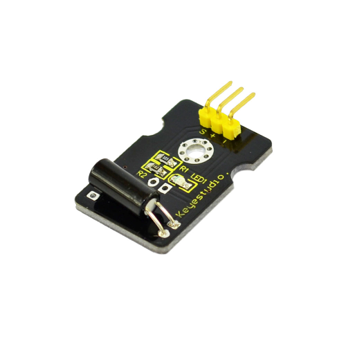
Project 7: Digital Tilt Sensor
Introduction:
Tilt Sensor is a digital tilt switch. It can be used as a simple tilt sensor. Simplly plug it to our IO/Sensor shield; you can make amazing interactive projects. With dedicated sensor shield and Arduino, you can achieve interesting and interactive work.
Specification:
Supply Voltage: 3.3V to 5V
Interface: Digital
Size: 30*20mm
Weight: 3g
Connection Diagram: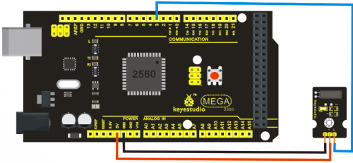
Sample Code:
int ledPin = 13;                // Connect LED to pin 13
int switcher = 3;                 // Connect Tilt sensor to Pin3

void setup()
{
  pinMode(ledPin, OUTPUT);      // Set digital pin 13 to output mode
  pinMode(switcher, INPUT);       // Set digital pin 3 to input mode
}
void loop()
{

   if(digitalRead(switcher)==HIGH) //Read sensor value
     {
        digitalWrite(ledPin, HIGH);   // Turn on LED when the sensor is tilted
     }
   else
     {
        digitalWrite(ledPin, LOW);    // Turn off LED when the sensor is not triggered
     }
}
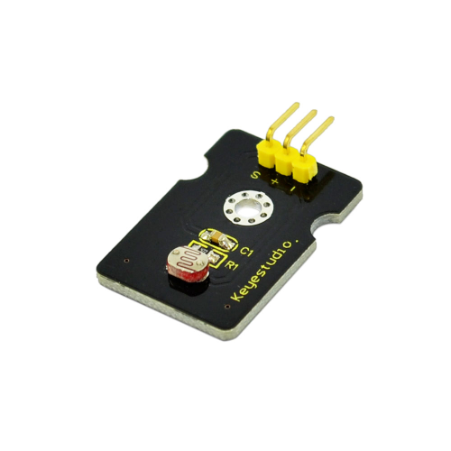
Project 8: Photocell sensor
Introduction:
Photocell is commonly seen in our daily life and is mainly used in intelligent switch, also in common electronic design. To make it easier and more effective, we supply corresponding modules.
Photocell is a semiconductor. It has features of high sensitivity, quick response, spectral characteristic, and R-value consistence, maintaining high stability and reliability in environment extremes such as high temperature, high humidity. It’s widely used in automatic control switch fields like cameras, garden solar lights, lawn lamps, money detectors, quartz clocks, music cups, gift boxes, mini night lights, sound and light control switches, etc.
Specification:
Interface type: analog
Working voltage: 5V
Size: 30*20mm
Weight: 3g
Connection Diagram:
Sample Code:
int sensorPin =A0 ;
int value = 0;
void setup()
{
 Serial.begin(9600); }

void loop()
{
 value = analogRead(sensorPin);
Serial.println(value, DEC);

delay(50); }
Project 9: Digital Push Button
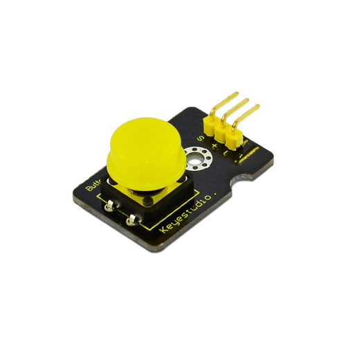
Introduction:
This is a basic application module. You can simply plug it into an IO shield to have your first taste of Arduino.
Advantages:
Wide voltage range from 3.3V to 5V
Standard assembling structure (two 3mm diameter holes with multiple of 5mm as distance from center)
Easily recognizable interfaces of sensors ("A" for analog and "D" for digital)
Icons illustrate sensor function clearly
High quality connector
Immersion gold surface
Specification:
Supply Voltage: 3.3V to 5V
Easy to 'plug and operate'
Large button keypad and high-quality first-class cap
Achieve interesting and interactive work
Interface: Digital
Size: 30*20mm
Weight: 4g
Connection Diagram: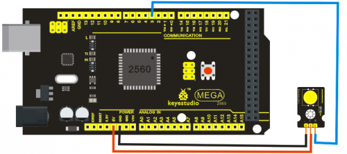
Sample Code:
/* # When you push the digital button, the Led 13 on the board will turn on. Otherwise,the led turns off.
*/
int ledPin = 13;                // choose the pin for the LED
int inputPin = 3;               // Connect sensor to input pin 3
void setup() {
  pinMode(ledPin, OUTPUT);      // declare LED as output
  pinMode(inputPin, INPUT);     // declare pushbutton as input
}
void loop(){
  int val = digitalRead(inputPin);  // read input value
  if (val == HIGH) {            // check if the input is HIGH
    digitalWrite(ledPin, LOW);  // turn LED OFF
  } else {
    digitalWrite(ledPin, HIGH); // turn LED ON
  }
}
Project 10: Capacitive Touch Sensor
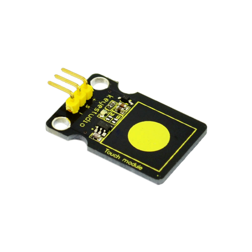
Introduction:
Are you tired of clicking mechanic button? Well, try our capacitive touch sensor. We can find touch sensors mostly on electronic device. So upgrade your Arduino project with our new version touch sensor and make it cool!!
This little sensor can "feel" people and metal touch and feedback a high/low voltage level. Even isolated by some cloth and paper, it can still feel the touch. Its sensetivity decrease as isolation layer gets thicker. For detail of usage, please check our wiki. To perfect user’s experience of our sensor module, we made following improvements.
Specification:
Supply Voltage: 3.3V to 5V
Interface: Digital
Size: 30*20mm
Weight: 3g
Connection Diagram: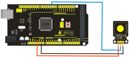
Sample Code:
int ledPin = 13;                // Connect LED on pin 13, or use the onboard one
int KEY = 2;                 // Connect Touch sensor on Digital Pin 2

void setup(){
  pinMode(ledPin, OUTPUT);      // Set ledPin to output mode
  pinMode(KEY, INPUT);       //Set touch sensor pin to input mode
}

void loop(){
   if(digitalRead(KEY)==HIGH) {      //Read Touch sensor signal
        digitalWrite(ledPin, HIGH);   // if Touch sensor is HIGH, then turn on
     }
   else{
        digitalWrite(ledPin, LOW);    // if Touch sensor is LOW, then turn off the led
     }
}
Project 11: DHT11 Temperature and Humidity Sensor
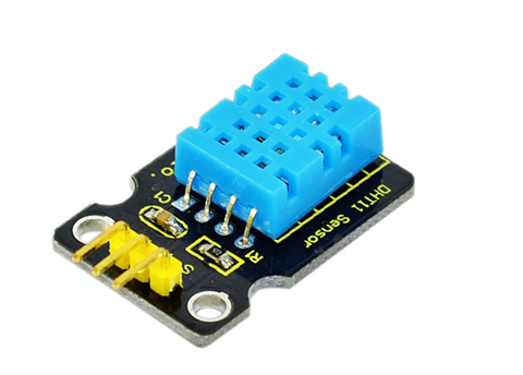
Introduction:
This DHT11 Temperature and Humidity Sensor features calibrated digital signal output with the temperature and humidity sensor complex. Its technology ensures high reliability and excellent long-term stability. A high-performance 8-bit microcontroller is connected. This sensor includes a resistive element and a sense of wet NTC temperature measuring devices. It has excellent quality, fast response, anti-interference ability and high cost performance advantages.
Each DHT11 sensor features extremely accurate calibration data of humidity calibration chamber. The calibration coefficients stored in the OTP program memory, internal sensors detect signals in the process, and we should call these calibration coefficients. The single-wire serial interface system is integrated to make it quick and easy. Qualities of small size, low power, and 20-meter signal transmission distance make it a wide applied application and even the most demanding one. Convenient connection, special packages can be provided according to users need.
Specification:
- Supply Voltage: +5 V
- Temperature range: 0-50 °C error of ± 2 °C
- Humidity: 20-90% RH ± 5% RH error
- Interface: Digital
- Size: 30*20mm
- Weight: 4g
Connection Diagram: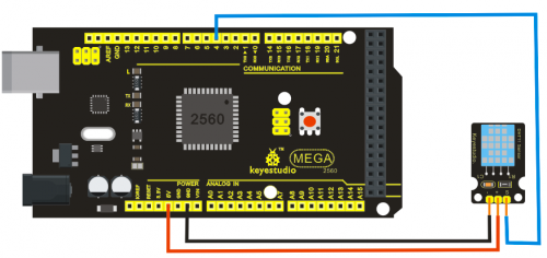
Sample Code:
Please download the DHT11Lib firstly.Or,see the website
#includedht11 DHT; #define DHT11_PIN 4 void setup(){ Serial.begin(9600); Serial.println("DHT TEST PROGRAM "); Serial.print("LIBRARY VERSION: "); Serial.println(DHT11LIB_VERSION); Serial.println(); Serial.println("Type,\tstatus,\tHumidity (%),\tTemperature (C)"); } void loop(){ int chk; Serial.print("DHT11, \t"); chk = DHT.read(DHT11_PIN); // READ DATA switch (chk){ case DHTLIB_OK: Serial.print("OK,\t"); break; case DHTLIB_ERROR_CHECKSUM: Serial.print("Checksum error,\t"); break; case DHTLIB_ERROR_TIMEOUT: Serial.print("Time out error,\t"); break; default: Serial.print("Unknown error,\t"); break; } // DISPLAT DATA Serial.print(DHT.humidity,1); Serial.print(",\t"); Serial.println(DHT.temperature,1); delay(1000); }
Project 12: Analog Sound Sensor
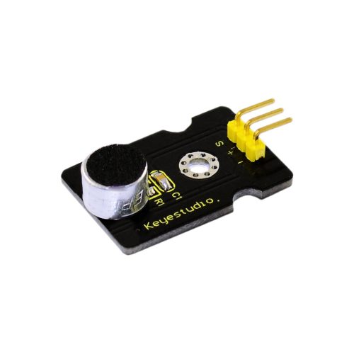
Introduction:
Analog Sound Sensor is typically used in detecting the loudness in ambient environment. The Arduino can collect its output signal by imitating the input interface. You can use it to make some interesting interactive works such as a voice operated switch.
Specification:
- Supply Voltage: 3.3V to 5V
- Detecting sound intensity
- Interface: Analog
- Size: 30*20mm
- Weight: 4g
Connection Diagram: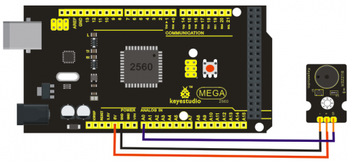
Sample Code:
void setup()
{
  Serial.begin(9600); // open serial port, set the baud rate to 9600 bps
}
void loop()
{
      int val;
      val=analogRead(0);   //connect mic sensor to Analog 0
      Serial.println(val,DEC);//print the sound value to serial
      delay(100);
}
Project 13: Flame Sensor
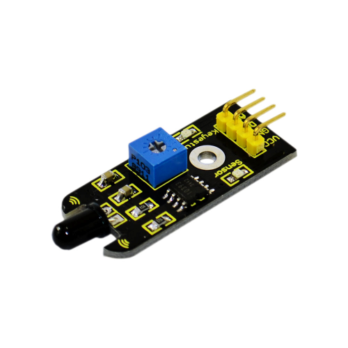
Introduction:
This flame sensor can be used to detect fire or other lights whose wavelength stands at 760 nm ~ 1100 nm. In the fire-fighting robot game, the flame plays an important role in the probe, which can be used as the robot's eyes to find fire source.
Specification:
- Supply Voltage: 3.3V to 5V
- Detection range: 20cm (4.8V) ~ 100cm (1V)
- Rang of Spectral Bandwidth: 760nm to 1100nm
- Operating temperature: -25?to 85?
- Interface: digital
- Size: 44*16.7mm
- Weight: 4g
Connection Diagram: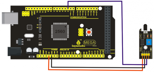
Sample Code:
const int flamePin = 2;     // the number of the flame pin
const int ledPin =  13;      // the number of the LED pin
// variables will change:
int State = 0;         // variable for reading status
void setup() {
  // initialize the LED pin as an output:
  pinMode(ledPin, OUTPUT);
  // initialize the pushbutton pin as an input:
  pinMode(flamePin, INPUT);
}
void loop(){
  // read the state of the value:
State = digitalRead(flamePin);
  if (State == HIGH) {

    // turn LED on:
    digitalWrite(ledPin, HIGH);
  }
  else {
    // turn LED off:
    digitalWrite(ledPin, LOW);
  }
}
Project 14: DS3231 Clock Module
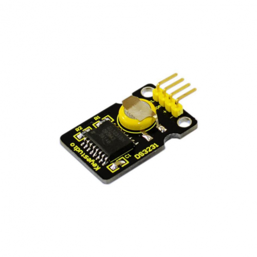
Introduction:
DS3231 is equipped with integrated TCXO and crystal, which makes it a cost-effective I2C real time clock with high precision. The device carries a battery input, so if you disconnect the main power supply, it can still maintain accurate timing. The integrated oscillator ensures the long-term accuracy of the device and reduces the number of components. DS3231 provides both commercial and industrial temperature range and supports 16 pins small-outline package (300mil). The module itself can adapt to the system of 3.3V and 5V without level switch, which is quite convenient!
Specification:
- Temperature range: -40 to +85; Timing accuracy : ± 5ppm (±0.432 seconds / day)
- Provide battery backup for continuous timing
- Low power consumption
- Device package and function compatible with DS3231
- Complete clock calendar function contains seconds and minutes, hour, week, date, month, and year timing and provides leap year compensation until 2100.
- Two calendar clock
- Output: 1Hz and 32.768kHz
- Reset output and Input Debounce of Pushbutton
- High speed (400kHz), I2C serial bus
- Supply voltage: +3.3V to +5.5V
- Digital temperature sensor with a precision of±3?
- Working temperature: -40 ~ C to +85 ~ C
- 16 pins Small Outline Package (300mil)
- Certified by American Association of Underwriters Laboratories (UL)
- Size: 30*20mm
- Weight: 4g
Connection Diagram:
This module adopts the IIC test method, so we only need to connect ‘SDA’ to Arduino A4, ‘SCL’ to A5, ‘+’ to VCC and ‘-’ to GND as follows: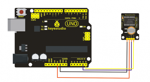
Sample Code:
#include#include "DS3231.h" DS3231 RTC; //Create the DS3231 object char weekDay[][4] = {"Sun", "Mon", "Tue", "Wed", "Thu", "Fri", "Sat" }; //year, month, date, hour, min, sec and week-day(starts from 0 and goes to 6) //writing any non-existent time-data may interfere with normal operation of the RTC. //Take care of week-day also. DateTime dt(2011, 11, 10, 15, 18, 0, 5);//open the series port and you can check time here or make a change to the time as needed. void setup () { Serial.begin(57600);//set baud rate to 57600 Wire.begin(); RTC.begin(); RTC.adjust(dt); //Adjust date-time as defined 'dt' above } void loop () { DateTime now = RTC.now(); //get the current date-time Serial.print(now.year(), DEC); Serial.print('/'); Serial.print(now.month(), DEC); Serial.print('/'); Serial.print(now.date(), DEC); Serial.print(' '); Serial.print(now.hour(), DEC); Serial.print(':'); Serial.print(now.minute(), DEC); Serial.print(':'); Serial.print(now.second(), DEC); Serial.println(); Serial.print(weekDay[now.dayOfWeek()]); Serial.println(); delay(1000); }
results:
Before compiling the code, you’d better put DS3231 library under file into Arduino catalogue,. When the above steps are done, you can upload the code to arduino and open the series monitor and get following results: 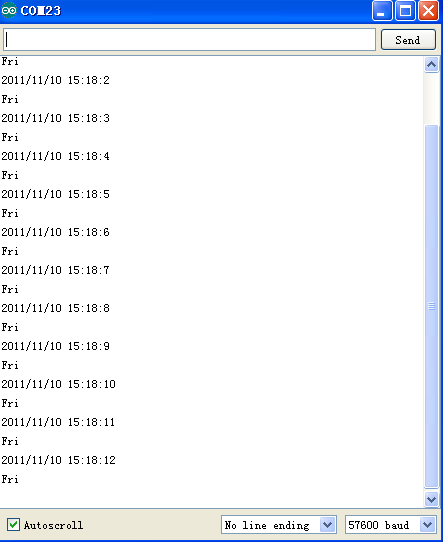
Project 15: Analog Gas Sensor
Introduction:
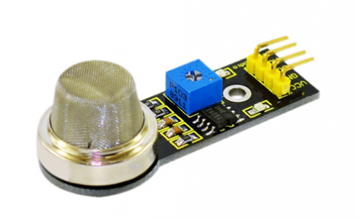
This analog gas sensor - MQ2 is used in gas leakage detecting equipment in consumer electronics and industrial markets. This sensor is suitable for detecting LPG, I-butane, propane, methane, alcohol, Hydrogen and smoke. It has high sensitivity and quick response. In addition, the sensitivity can be adjusted by the potentiometer.
Specification:
- Power supply: 5V
- Interface type: Analog
- Wide detecting scope
- Quick response and High sensitivity
- Simple drive circuit
- Stable and long lifespan
- Size: 49.7*20mm
- Weight: 8g
Connection Diagram: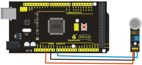
Sample Code:
///Arduino Sample Code
void setup()
{
  Serial.begin(9600); //Set serial baud rate to 9600 bps
}
void loop()
{
int val;
val=analogRead(0);//Read Gas value from analog 0
Serial.println(val,DEC);//Print the value to serial port
delay(100);
}
Project 16: Analog Alcohol Sensor
Introduction:
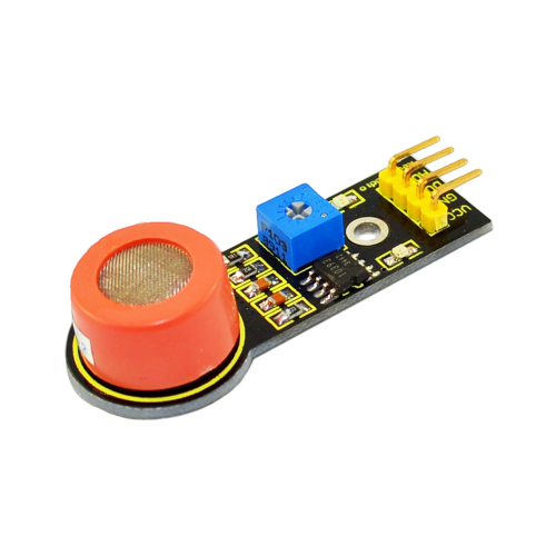
This analog gas sensor - MQ3 is suitable for detecting alcohol. It can be used in a Breath analyzer. Also it has high sensitivity to alcohol and low sensitivity to Benzine. The sensitivity can be adjusted by the potentiometer.
Specification:
- Power supply: 5V
- Interface type: Analog
- Quick response and High sensitivity
- Simple drive circuit
- Stable and long service life
- Size: 49.7*20mm
- Weight: 6g
Connection Diagram: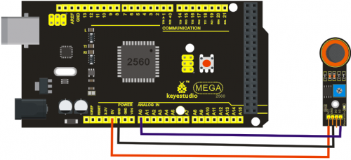
Sample Code:
///Arduino Sample Code
void setup()
{
  Serial.begin(9600); //Set serial baud rate to 9600 bps
}
void loop()
{
int val;
val=analogRead(0);//Read Gas value from analog 0
Serial.println(val,DEC);//Print the value to serial port
delay(100);
}
Project 17: keyestudio Water Sensor
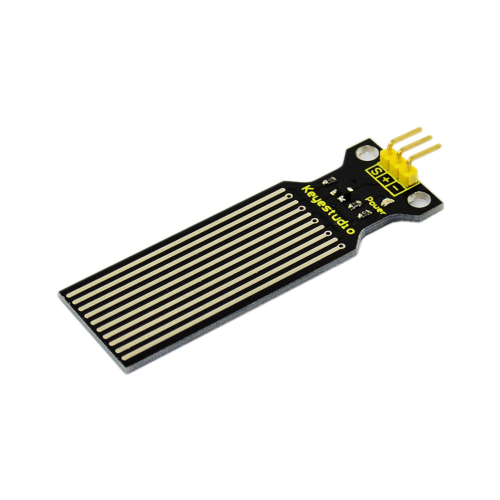
Introduction:
Our water sensor is easy- to-use, portable and cost-effective designed to identify and detect water level and water drop. This sensor measures the volume of water drop and water quantity through an array of traces of exposed parallel wires. Compared with its competitors, this sensor is not only smaller and smarter but also ingeniously equipped with following features:
- smooth conversion between water quantity and analog quantity;
- strong flexibility, this sensor outputs basic analog value;
- low power consumption and high sensitivity;
- directly connected to microprocessor or other logic circuits, suitable for a variety of development boards and controllers such as Arduino controller, STC single-chip microcomputer, AVR single-chip microcomputer etc.
Specification:
- Product name: Water Sensor
- Operating voltage: DC5V
- Operating current: ?20mA
- Sensor type: Analog
- Detection area: 40mm x16mm
- Production process: FR4 double-side tinned
- Humanized design: Anti-slippery semi-lunar recess
- Operating temperature: 10%~90% without condensation
- Product weight: 3g
- Product size: 65mm x 20mm x 8mm
Connection Diagram: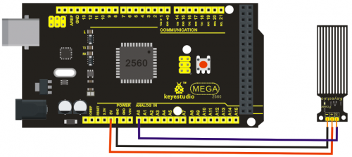
Sample Code:
int analogPin = 0; //connect water sensor to analog interface 0
int led = 13; //LED to digital interface 13
int val = 0; //define the initial value of variable ‘val’ as 0
int data = 0; //define the initial value of variable ‘data’ as 0
void setup()
{
pinMode(led, OUTPUT); //define led as output pin
Serial.begin(9600); //set baud rate at 9600
}
void loop()
{
val = analogRead(analogPin); //read and assign analog value to variable ’val’
if(val>700){ //decide whether variable ‘val’ is over 700 digitalWrite(led,HIGH); //turn on  LED when variable ‘val’ is over 700
}
else{
digitalWrite(led,LOW); //turn off LED when variable ‘val’ is under 700
}
data = val; //variable ’val’ assigns value to variable ‘data’
Serial.println(data); //print variable ‘data’ by Serial.print
delay(100);
}
After the above steps are done, let’s do a test on lower water level and check what happens:
The LED can’t light up when water level haven’t reach alarm value;
The LED turns on and released an alarm when water level reaches alarm value;
Project 18: Soil Humidity Sensor
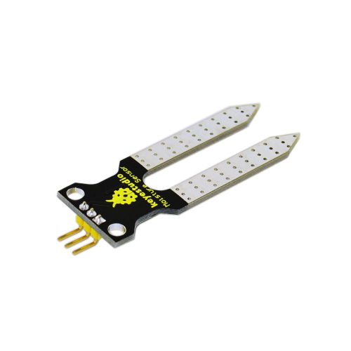
Introduction:
This is a simple soil humidity sensor aims to detect the soil humidity. If the soil is in lack of water, the analog value output by the sensor will decrease, otherwise, it will increase. If you use this sensor to make an automatic watering device, it can detect whether your botany is thirsty to prevent it from withering when you go out. Using the sensor with Arduino controller makes your plant more comfortable and your garden smarter.
The soil humidity sensor module is not as complicated as you might think, and if you need to detect the soil in your project , it will be your best choice.
The sensor is set with two probes inserted into the soil, then with the current go through the soil, the sensor will get resistance value by reading the current changes between the two probes and convert such resistance value into moisture content. The higher moisture (less resistance), the higher conductivity the soil has.
The surface of the sensor have undergone metallization process to prolong its service life. Insert it into the soil and then use the AD converter to read it. With the help of this sensor, the plant can remind you: I need water.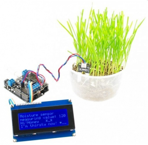
Specification:
- Power Supply Voltage: 3.3V or 5V
- Working Current: ? 20mA
- Output Voltage: 0-2.3V (When the sensor is totally immersed in water, the
- voltage will be 2.3V) 5V power supply,the higher humidity, the higher the output voltage
- Packaging : Electrostatic bag sealing
- Sensor type: Analog output
- Interface definition: Pin1- signal, pin2- GND, pin3 - VCC
- Service life: About one year (gold-plated surface for enhancing conductivity and corrosion resistance )
- Module size: 20X60mm
Connection Diagram: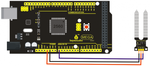
Sample Code:
/*
  # Example code for the moisture sensor
  # Connect the sensor to the A0(Analog 0) pin on the Arduino board
  # the sensor value description
  # 0  ~300     dry soil
  # 300~700     humid soil
  # 700~950     in water
*/
void setup(){
  Serial.begin(57600);
}
void loop(){
  Serial.print("Moisture Sensor Value:");
  Serial.println(analogRead(0));
  delay(100);
}
Project 19: Infrared Obstacle Avoidance Sensor
Introduction:
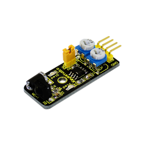
Infrared obstacle avoidance sensor is equipped with distance adjustment function and is especially designed for wheeled robots. This sensor has strong adaptability to ambient light and is of high precision. It has a pair of infrared transmitting and receiving tube. When infrared ray launched by the transmitting tube encounters an obstacle (its reflector), the infrared ray is reflected to the receiving tube, and the indicator will light up; the signal output interface outputs digital signal. We can adjust the detection distance through the potentiometer knob ( effective distance: 2~40cm, working Voltage: 3.3V-5V ). Thanks to a wide voltage range, this sensor can work steadily even under fluctuating power supply voltage and is suitable for the use of various micro-controllers, Arduino controllers and BS2 controllers. A robot mounted with the sensor can sense changes in the environment.
Specification:
- Working voltage: DC 3.3V-5V
- Working current: ?20mA
- Working temperature: -10?—+50?
- Detection distance: 2-40cm
- IO Interface: 4 wire interface (-/+/S/EN)
- Output signal: TTL voltage
- Accommodation mode: Multi-circle resistance regulation
- Effective Angle: 35°
- Size: 41.7*16.7mm
- Weight: 5g
Connection Diagram: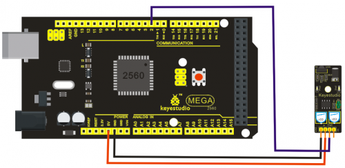
Sample Code:
const int flamePin = 2;     // the number of the flame pin
const int ledPin =  13;      // the number of the LED pin
// variables will change:
int State = 0;         // variable for reading status
void setup() {
  // initialize the LED pin as an output:
  pinMode(ledPin, OUTPUT);
  // initialize the pushbutton pin as an input:
  pinMode(flamePin, INPUT);
}
void loop(){
  // read the state of the value:
State = digitalRead(flamePin);
  if (State == HIGH) {

    // turn LED on:
    digitalWrite(ledPin, HIGH);
  }
  else {
    // turn LED off:
    digitalWrite(ledPin, LOW);
  }
}
Project 20: PIR Motion Sensor
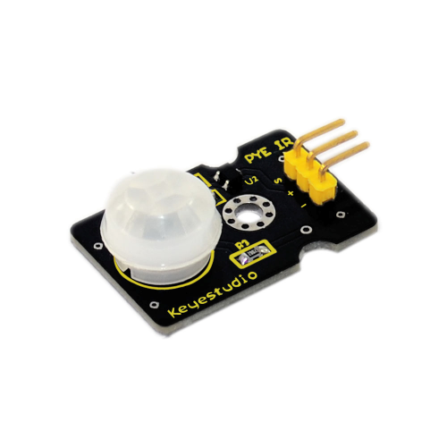
Introduction:
Pyroelectric infrared motion sensor can detect infrared signals from a moving person or moving animal, and output switching signals. It can be applied to a variety of occasions to detect the movement of human body. Conventional pyroelectric infrared sensors require body pyroelectric infrared detector, professional chip, complex peripheral circuit, so the size is bigger, with complex circuit, and lower reliability. Now we launch this new pyroelectric infrared motion sensor, specially designed for Arduino. It uses an integrated digital body pyroelectric infrared sensor, has smaller size, higher reliability, lower power consumption and simpler peripheral circuit.
Specification:
- Input Voltage: 3.3 ~ 5V, 6V Maximum
- Working Current: 15uA
- Working Temperature: -20 ~ 85 ?
- Output Voltage: High 3V, low 0V
- Output Delay Time (High Level): About 2.3 to 3 Seconds
- Detection angle: 100 °
- Detection distance: 7 meters
- Output Indicator LED (When output HIGH, it will be ON)
- Pin limit current: 100mA
- Size: 30*20mm
- Weight: 4g
Connection Diagram: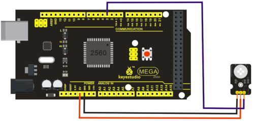
Sample Code:
byte sensorPin = 3;
byte indicator = 13;
void setup()
{
  pinMode(sensorPin,INPUT);
  pinMode(indicator,OUTPUT);
  Serial.begin(9600);
}
void loop()
{
  byte state = digitalRead(sensorPin);
  digitalWrite(indicator,state);
  if(state == 1)Serial.println("Somebody is in this area!");
  else if(state == 0)Serial.println("No one!");
  delay(500);
}
Project 21: Joystick Module
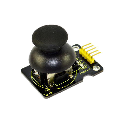
Introduction:
Lots of robot projects need joystick. This module provides an affordable solution. By simply connecting to two analog inputs, the robot is at your commands with X, Y control. It also has a switch that is connected to a digital pin. This joystick module can be easily connected to Arduino by IO Shield. This module is for Arduino(V5) with cables supplied.
Specification:
- Supply Voltage: 3.3V to 5V
- Interface: Analog x2, Digital x1
- Size: 40*28mm
- Weight: 12g
Connection Diagram:
Sample Code:
int JoyStick_X = 0; //x
int JoyStick_Y = 1; //y
int JoyStick_Z = 3; //key

void setup()
{
  pinMode(JoyStick_Z, INPUT);
  Serial.begin(9600); // 9600 bps
}
void loop()
{
  int x,y,z;
  x=analogRead(JoyStick_X);
  y=analogRead(JoyStick_Y);
  z=digitalRead(JoyStick_Z);
  Serial.print(x ,DEC);
  Serial.print(",");
  Serial.print(y ,DEC);
  Serial.print(",");
  Serial.println(z ,DEC);
  delay(100);
}
Project 22: Photo interrupter module
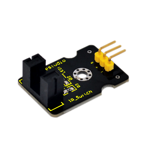
Introduction:
Upright part of this sensor is an infrared emitter and on the other side, it’s a shielded infrared detector. By emitting a beam of infrared light from one end to other end, the sensor can detect an object when it passes through the beam. It is used for many applications including optical limit switches, pellet dispensing, general object detection, etc.
Specification:
- Supply Voltage: 3.3V to 5V
- Interface: Digital
- Size: 30*20mm
- Weight: 3g
Connection Diagram: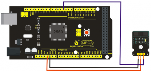
Sample Code:
// photo interrupter module

int Led = 13 ;// define LED Interface
int buttonpin = 3; // define the photo interrupter sensor interface
int val ;// define numeric variables val
void setup ()
{
  pinMode (Led, OUTPUT) ;// define LED as output interface
  pinMode (buttonpin, INPUT) ;// define the photo interrupter sensor output interface
}
void loop ()
{
  val = digitalRead (buttonpin) ;// digital interface will be assigned a value of 3 to read val
  if (val == HIGH) // When the light sensor detects a signal is interrupted, LED flashes
  {
    digitalWrite (Led, HIGH);
  }
  else
  {
    digitalWrite (Led, LOW);
  }
}
Project 23: 5V Relay Module
Introduction:
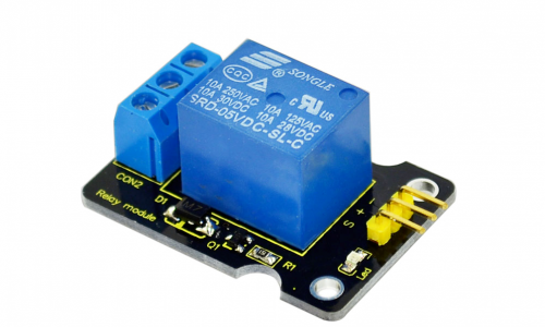
This single relay module can be used in interactive projects. This module uses SONGLE 5v high-quality relay. It can also be used to control lighting, electrical and other equipment. The modular design makes it easy to expand with the Arduino board (not included). The Relay output is by a light-emitting diode. It can be controlled through digital IO port, such as solenoid valves, lamps, motors and other high current or high voltage devices.
Specification:
- Type: Digital
- Rated current: 10A (NO) 5A (NC)
- Maximum switching voltage: 150VAC 24VDC
- Digital interface
- Control signal: TTL level
- Rated load: 8A 150VAC (NO) 10A 24VDC (NO), 5A 250VAC (NO/NC) 5A 24VDC (NO/NC)
- Maximum switching power: AC1200VA DC240W (NO) AC625VA DC120W (NC)
- Contact action time: 10ms
- Size: 40*28mm
- Weight: 15g
Connection Diagram: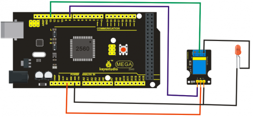
Sample Code:
  int Relay = 8;
  void setup()
{
  pinMode(13, OUTPUT);         //Set Pin13 as output
  digitalWrite(13, HIGH);     //Set Pin13 High
  pinMode(Relay, OUTPUT);     //Set Pin3 as output
}
void loop()
{
          digitalWrite(Relay, HIGH);   //Turn off relay
          delay(2000);
          digitalWrite(Relay, LOW);    //Turn on relay
          delay(2000);
}
Project 24: ADXL345 Three Axis Acceleration Module
Introduction:
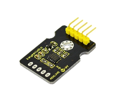
The ADXL345 is a small, thin, low power, 3-axis MEMS accelerometer with high resolution (13-bit) measurement at up to +-16 g. Digital output data is formatted as 16-bit twos complement and is accessible through either a SPI (3- or 4-wire) or I2C digital interface.
The ADXL345 is well suited to measures the static acceleration of gravity in tilt-sensing applications, as well as dynamic acceleration resulting from motion or shock. Its high resolution (4 mg/LSB) enables measurement of inclination changes less than 1.0 degrees.
Specification:
- 2.0-3.6VDC Supply Voltage
- Ultra Low Power: 40uA in measurement mode, 0.1uA in standby@ 2.5V
- Tap/Double Tap Detection
- Free-Fall Detection
- SPI and I2C interfaces
- Size: 30*20mm
- Weight: 3g
Connection Diagram: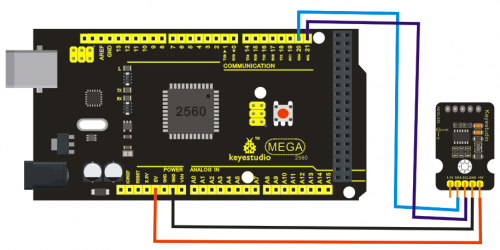
Sample Code:
/* The circuit: VCC: 5V GND: ground SCL: UNO SLC SDA: UNO SDA This example code is in the public domain. */ #include// Registers for ADXL345 #define ADXL345_ADDRESS (0xA6 >> 1) // address for device is 8 bit but shift to the // right by 1 bit to make it 7 bit because the // wire library only takes in 7 bit addresses #define ADXL345_REGISTER_XLSB (0x32) int accelerometer_data[3]; // void because this only tells the cip to send data to its output register // writes data to the slave's buffer void i2c_write(int address, byte reg, byte data) { // Send output register address Wire.beginTransmission(address); // Connect to device Wire.write(reg); // Send data Wire.write(data); //low byte Wire.endTransmission(); } // void because using pointers // microcontroller reads data from the sensor's input register void i2c_read(int address, byte reg, int count, byte* data) { // Used to read the number of data received int i = 0; // Send input register address Wire.beginTransmission(address); // Connect to device Wire.write(reg); Wire.endTransmission(); // Connect to device Wire.beginTransmission(address); // Request data from slave // Count stands for number of bytes to request Wire.requestFrom(address, count); while(Wire.available()) // slave may send less than requested { char c = Wire.read(); // receive a byte as character data[i] = c; i++; } Wire.endTransmission(); } void init_adxl345() { byte data = 0; i2c_write(ADXL345_ADDRESS, 0x31, 0x0B); // 13-bit mode +_ 16g i2c_write(ADXL345_ADDRESS, 0x2D, 0x08); // Power register i2c_write(ADXL345_ADDRESS, 0x1E, 0x00); // x i2c_write(ADXL345_ADDRESS, 0x1F, 0x00); // Y i2c_write(ADXL345_ADDRESS, 0x20, 0x05); // Z // Check to see if it worked! i2c_read(ADXL345_ADDRESS, 0X00, 1, &data); if(data==0xE5) Serial.println("it work Success"); else Serial.println("it work Fail"); } void read_adxl345() { byte bytes[6]; memset(bytes,0,6); // Read 6 bytes from the ADXL345 i2c_read(ADXL345_ADDRESS, ADXL345_REGISTER_XLSB, 6, bytes); // Unpack data for (int i=0;i<3;++i) { accelerometer_data[i] = (int)bytes[2*i] + (((int)bytes[2*i + 1]) << 8); } } // initialise and start everything void setup() { Wire.begin(); Serial.begin(9600); for(int i=0; i<3; ++i) { accelerometer_data[i] = 0; } init_adxl345(); } void loop() { read_adxl345(); Serial.print("ACCEL: "); Serial.print(float(accelerometer_data[0])*3.9/1000);//3.9mg/LSB scale factor in 13-bit mode Serial.print("\t"); Serial.print(float(accelerometer_data[1])*3.9/1000); Serial.print("\t"); Serial.print(float(accelerometer_data[2])*3.9/1000); Serial.print("\n"); delay(100); }
Project 25: Rotary Encoder module
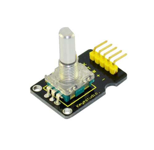
Introduction:
The rotary encoder can count the pulse outputting times during the process of its rotation in positive and reverse direction by rotating. This rotating counting is unlimited, not like potential counting. It can be restored to initial state to count from 0 with the button on rotary encoder.
Specification:
- Power Supply: 5V
- Interface: Digital
- Size: 30*20mm
- Weight: 7g
Connection Diagram: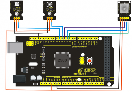
Sample Code:
const int interruptA = 0;
const int interruptB = 1;
int CLK = 2;     // PIN2
int DAT = 3;     // PIN3
int BUTTON = 4;  // PIN4
int LED1 = 5;    // PIN5
int LED2 = 6;    // PIN6
int COUNT = 0;

void setup()
 {
  attachInterrupt(interruptA, RoteStateChanged, FALLING);
 // attachInterrupt(interruptB, buttonState, FALLING);
  pinMode(CLK, INPUT);
  digitalWrite(2, HIGH);  // Pull High Restance
  pinMode(DAT, INPUT);
  digitalWrite(3, HIGH);  // Pull High Restance
  pinMode(BUTTON, INPUT);
  digitalWrite(4, HIGH);  // Pull High Restance
  pinMode(LED1, OUTPUT);
  pinMode(LED2, OUTPUT);
   Serial.begin(9600);
 }

void loop()
{
  if  (!(digitalRead(BUTTON)))
    {
     COUNT = 0;
     Serial.println("STOP COUNT = 0");
     digitalWrite(LED1, LOW);
     digitalWrite(LED2, LOW);
     delay (2000);
    }
     Serial.println(COUNT);
}

//-------------------------------------------
void RoteStateChanged() //When CLK  FALLING READ DAT
{
 if  (digitalRead(DAT)) // When DAT = HIGH IS FORWARD
   {
    COUNT++;
    digitalWrite(LED1, HIGH);
    digitalWrite(LED2, LOW);
    delay(20);
   }
 else                   // When DAT = LOW IS BackRote
   {
    COUNT--;
    digitalWrite(LED2, HIGH);
    digitalWrite(LED1, LOW);
    delay(20);
   }
}
Project 26: Analog Rotation Sensor
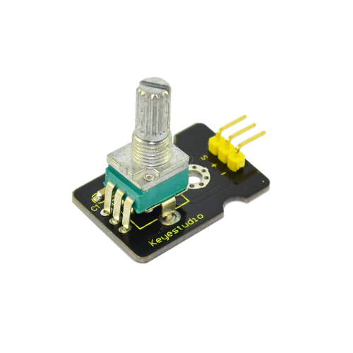
Introduction:
This analog Rotation Sensor is arduino compatible. It is based on a potentiometer. Its voltage can be subdivided into 1024, easy to be connected to Arduino with our sensor shield. Combined with other sensors, we can make interesting projects by reading the analog value from the IO port.
Specification:
- Supply Voltage: 3.3V to 5V
- Interface: Analog
- Size: 30*20mm
- Weight: 8g
Connection Diagram: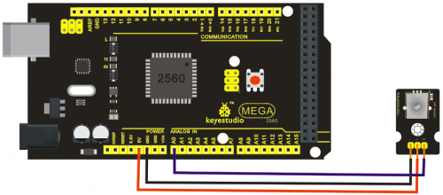
Sample Code:
///Arduino Sample Code
void setup()
{
  Serial.begin(9600); //Set serial baud rate to 9600 bps
}
void loop()
{
int val;
val=analogRead(0);//Read rotation sensor value from analog 0
Serial.println(val,DEC);//Print the value to serial port
delay(100);
}
Project 27: HC-SR04 Ultrasonic Sensor
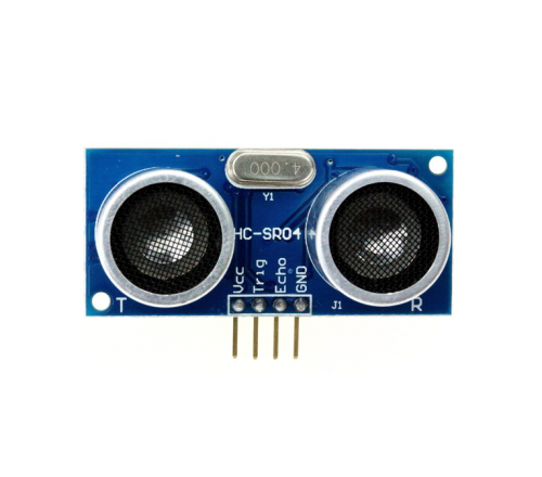
Introduction:
The HC-SR04 Ultrasonic Sensor is a very affordable proximity/distance sensor that has been used mainly for object avoidance in various robotics projects. It essentially gives your Arduino eyes / spacial awareness and can prevent your robot from crashing or falling off a table. It has also been used in turret applications, water level sensing, and even as a parking sensor. This simple project will use the HC-SR04 sensor with an Arduino and a Processing sketch to provide a neat little interactive display on your computer screen.
Specification:
- Working Voltage: DC 5V
- Working Current: 15mA
- Working Frequency: 40Hz
- Max Range: 4m
- Min Range: 2cm
- Measuring Angle: 15 degree
- Trigger Input Signal: 10µS TTL pulse
- Echo Output Signal Input TTL lever signal and the range in proportion
- Size: 46*20.4mm
- Weight: 9g
Connection Diagram: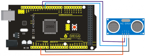
Sample Code:
VCC to arduino 5v
GND to arduino GND
Echo to Arduino pin 7
Trig to Arduino pin 8
#define echoPin 7 // Echo Pin
#define trigPin 8 // Trigger Pin
#define LEDPin 13 // Onboard LED

int maximumRange = 200; // Maximum range needed
int minimumRange = 0; // Minimum range needed
long duration, distance; // Duration used to calculate distance

void setup() {
 Serial.begin (9600);
 pinMode(trigPin, OUTPUT);
 pinMode(echoPin, INPUT);
 pinMode(LEDPin, OUTPUT); // Use LED indicator (if required)
}

void loop() {
/* The following trigPin/echoPin cycle is used to determine the
 distance of the nearest object by bouncing soundwaves off of it. */
 digitalWrite(trigPin, LOW);
 delayMicroseconds(2);

 digitalWrite(trigPin, HIGH);
 delayMicroseconds(10);

 digitalWrite(trigPin, LOW);
 duration = pulseIn(echoPin, HIGH);

 //Calculate the distance (in cm) based on the speed of sound.
 distance = duration/58.2;

 if (distance >= maximumRange || distance <= minimumRange){
 /* Send a negative number to computer and Turn LED ON
 to indicate "out of range" */
 Serial.println("-1");
 digitalWrite(LEDPin, HIGH);
 }
 else {
 /* Send the distance to the computer using Serial protocol, and
 turn LED OFF to indicate successful reading. */
 Serial.println(distance);
 digitalWrite(LEDPin, LOW);
 }

 //Delay 50ms before next reading.
 delay(50);
}
Project 28: Pulse Rate Monitor
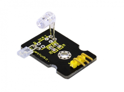
Introduction:
This module uses a ultra-bright infrared (IR) LED and a phototransistor to detect the pulse in your finger. The red LED then flashes in time with your pulse.
Working principle: Shine the bright LED onto one side of your finger while the phototransistor on the other side of your finger picks up the amount of transmitted light. The resistance of the phototransistor will vary slightly as the blood pulses through your finger.
Connection Diagram: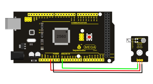
Sample Code:
The program for this project is quite tricky to get right. Indeed, the first step is not to run the entire final script, but rather a test script that will gather data that we can then paste into a spreadsheet and chart to test out the smoothing algorithm (more on this later).
The test script is provided in Listing Project 12.
int ledPin = 13;
int sensorPin = 0;
double alpha = 0.75;
int period = 20;
double change = 0.0;
void setup()
{
pinMode(ledPin, OUTPUT);
Serial.begin(115200);
}
void loop()
{
static double oldValue = 0;
static double oldChange = 0;
int rawValue =
analogRead(sensorPin);
double value = alpha * oldValue
+ (1 - alpha) * rawValue;
Serial.print(rawValue);
Serial.print(",");
Serial.println(value);
oldValue = value;
delay(period);
}
This script reads the raw signal from the analog input and applies the smoothing function and then writes both values to the Serial Monitor, where we can capture them and paste them into a spreadsheet for analysis. Note that the Serial Monitor’scommunications is set to its fastest rate to minimize the effects of the delays caused by sending the data. When you start the Serial Monitor, you will need to change the serial speed to 115200 baud.
Copy and paste the captured text into a spreadsheet. The resultant data and a line chart drawn from the two columns are shown in Figure 5-17. The more jagged trace is from the raw data read from the analog port, and the smoother trace clearly has most of the noise removed. If the smoothed trace shows significant noise—in particular, any false peaks that will confuse the monitor—increase the level of smoothing by decreasing the value of alpha.
Once you have found the right value of alpha for your sensor arrangement, you can transfer this value into the real sketch and switch over to using the real sketch rather than the test sketch. The real sketch is provided in the following listing on the next page.
int ledPin = 13;
int sensorPin = 0;
double alpha = 0.75;
int period = 20;
double change = 0.0;
void setup()
{
pinMode(ledPin, OUTPUT);
Serial.begin(115200);
}
void loop()
{
static double oldValue = 0;
static double oldChange = 0;
int rawValue =
analogRead(sensorPin);
double value = alpha * oldValue
+ (1 - alpha) * rawValue;
Serial.print(rawValue);
Serial.print(",");
Serial.println(value);
oldValue = value;
delay(period);
}
LISTING PROJECT 12—TEST SCRIPT There now just remains the problem of detecting the peaks. Looking at Figure 5-17, we can see that if we keep track of the previous reading, we can see that the readings are gradually increasing until the change in reading flips over and becomes negative. So, if we lit the LED whenever the old change was positive but the new change was negative, we would get a brief pulse from the LED at the peak of each pulse. Putting It All Together Both the test and real sketch for Project 12 are in your Arduino Sketchbook. For instructions on downloading it to the board, see Chapter 1.
As mentioned, getting this project to work is a little tricky. You will probably find that you have to get your finger in just the right place to start getting a pulse. If you are having trouble, run the test script as described previously to check that your detector is getting a pulse and the smoothing factor alpha is low enough.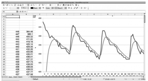
Project 29: Reed Switch Module
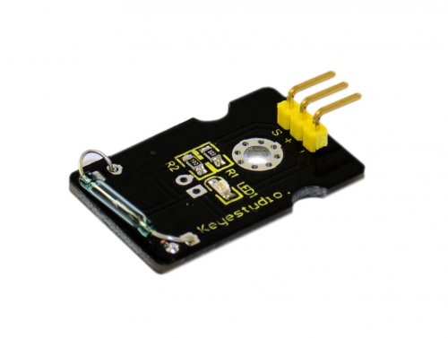
Introduction:
Reed Switch is a special switch and a main component for reed relay and proximity switch. Reed switch is usually comprised of two soft magnetic material and metal reed contacts which will disconnect itself when there is no magnetic. In addition, some reed switches are also equipped with another reed acting as the third normally-closed contact. These reed contacts are encapsulated in a glass tube full of inert gases(such as nitrogen and helium) or in a vacuum glass tube. The reeds encapsulated in the glass tube are placed in parallel with ends overlapped. Certain amount of space or mutual contaction will be reserved so as to constitute the normally-open or normally-closed contacts of the switch.
Reed switch can be used as sensor for count, limit and other purposes. For instance, a kind of bike-kilometer is constituted by sticking magnetic to the tire and mounting reed switch aside. We can mount reed switch on the door for alarming purpose or as switches.
Reed switch has been widely applied in household appliances, cars, communication, industry, healthcare and security areas. Furthermore, it can also be applied to other sensors and electric devices such as liquidometer, door magnet, reed relay, oil level sensor and proximity sensor(magnetic sensor). It can be used under high-risk environment.
Specification:
- Working voltage: DC 3.3V-5V
- Working current: ?20mA
- Working temperature: -10?—+50?
- Detection distance: ?10mm
- IO Interface: 3 wire interface (-/+/S)
- Size: 30*20mm
- Weight: 3g
Connection Diagram: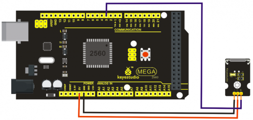
Sample Code:
int Led=13;//define LED interface
int buttonpin=3; //define magnetic ring sensor interface
int val;//define digital variable val
void setup()
{
pinMode(Led,OUTPUT);//define LED as output interface
pinMode(buttonpin,INPUT);//define magnetic ring sensor as output interface
}
void loop()
{
val=digitalRead(buttonpin);// read and assign the value of digital interface 3 to val
if(val==HIGH)//When a signal is detected by magnetic ring sensor, LED will flash
{
digitalWrite(Led,HIGH);
}
else
{
digitalWrite(Led,LOW);
}
}
Project 30: TEMT6000 ambient light sensor
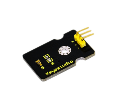
Introduction:
At some point you are going to want to sense ambient brightness with better precision than your trusty photoresistor without adding complexity to your project. When that day comes, go get yourself a TEMT6000 ambient light sensor.
The TEMT6000 is supposed to be adapted to the sensitivity of the human eye, but I found it preformed sub-par in low light conditions. It does however work very well reacting to very small changes in a large range of brightnesses. Because it is meant to mimic the human eye, it does not react well to IR or UV light, so just make sure to note that when considering using it in your project.
Specification:
- Supply Voltage: +5VDC 50mA
- Size: 36.5*16mm
- Weight: 4g
Connection Diagram:
This is an incredibly simple part, just connect power and ground, and the signal pin to your favorite analog input and you are done, the sensor will output analog voltage, that ramps up when it gets brighter. You can power this off of 3.3v if you would like, the output value will just be lower.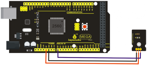
Sample Code:
You can not get more simple than this – This just reports the reading from the sensor to the serial terminal: 0-1023 with 1023 being very bright, and 0 being very dark.
int temt6000Pin = 0;
void setup() {
 Serial.begin(9600);
}
void loop() {
 int value = analogRead(temt6000Pin);
 Serial.println(value);
 delay(100); //only here to slow down the output so it is easier to read
}
Resources / Kaynaklar
Video
http://www.keyestudio.com/wp/ks0083-84-kit/
https://drive.google.com/open?id=1pG86G771c0UoytBCd0H518evWMn1F39I

